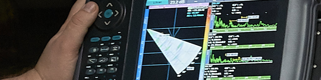
AnyScan 30 - Flaw Detector
 Ultrasonic Non-Destructive Testing employs ultrasonic waves transmitted into a test component to search for sub-surface defects. UT can be utilised on many different materials such as steel, plastics, ceramics and composites. The types of defect that can be found include discontinuities, porosity, slag, inclusions and cavities.
The Anyscan-30 Flaw Detector is an easy to use yet powerful and reliable instrument that can determine defects in a variety of materials allowing rapid assessment, diagnosis and reporting. An Anyscan-30 is ideal for use in Flaw Detection and Quality control applications.
Careful thought was applied to keystroke use and menu options. Regularly used functions are allocated specific keys. Multiple on-board reporting tools and a comprehensive data filing system enable you to easily collect and report high quality inspection data.
Anyscan-30 is equipped with lithium batteries with an operation time of more than 8 hours. This makes the Anyscan-30 a perfect choice for on-site testing for either novice or experienced inspectors.
Features
The Anyscan-30 unit includes a full set of shear wave probes, compression probe and cables as standard providing exceptional value in today’s competitive market.
- 400 MHz real-time hardware sampling, high-fidelity echo pulse
- Low noise broadband & amplifying circuits with selectable damping.
- Standard dynamic DAC/TCG and onboard DGS/AVG.
- Designed to meet the requirements of EN12668-1.
- Intuitive keys location and menus, creating easy operation.
- Weld Graph Displaying Function with on screen representation.
- Continuously Storing and Replaying Function playback capability.
- Excellent EMI design, good EMC performance.
- 5.7〞high resolution color LCD display.
System Operation
- DAC file, Store and Recall
- AVG Make, Store and Recall
- Envelope
- Weld Graph Display
- RF Display
- Curve Surface Amending
- Peak Hold
- Automatic Echo Spectrum Test
- Auto Gain Adjustment
- Intelligent Calibration Procedures
- Quick Channel Setup
- Automatic Report Generation
- Dynamic Waveform Store and Recall
- Waveform Zoom
- Gate Zoom
-
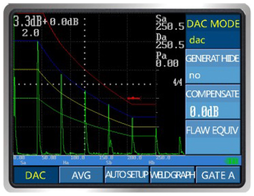
DAC file, Store and Recall
A quick and easy operation - When connecting sample points one by one, it will automatically draw four lines such as “Assess Line”, “RATINE Line”, “GENERATRIX Line” and “Void Line”. Easy to convert to different worldwide standards by dynamically adding sample points and adjusting curve offset accordingly. -
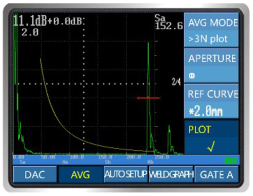
AVG Make, Store and Recall
AVG is flaw sizing technique that allows echo signals to be evaluated with a DGS/AVG representation associated to a particular type of probe and material. The DGS/AVG diagram illustrates the relationships between echo height, flaw size, and distance from the probe. It can automatically adjust the curve equivalent and calculate the flaw equivalent size Φ automatically. -
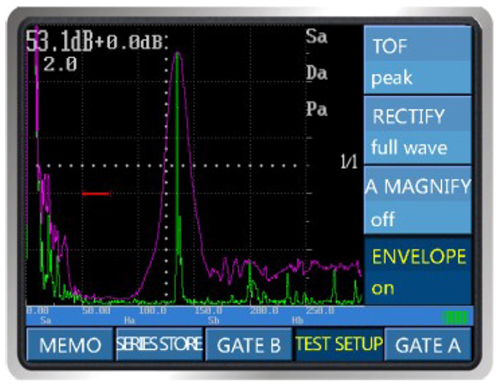
Envelope
Records changing echo profile -
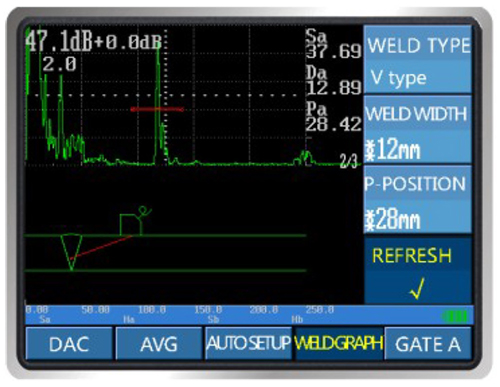
Weld Graph Display
The Weld Graph Display Function allows the inspector to visualise the sound path within the component being inspected. This makes the flaw position obvious within the weld profile. The graphs can be stored in the flaw detection report, which can be replayed and printed. -
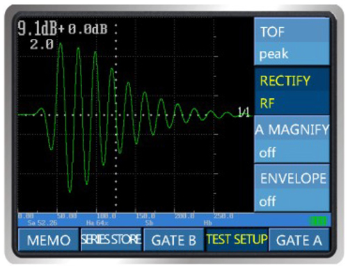
RF Display
Displays the original waveform, allowing the operator to analyze the echo in detail and help to quantify the flaw. -
Curve Surface Amending
For normal flat plate inspections simples trigonometry can be used to determine leg length, reflector depth, and surface distance from the probe index point. By utilising a software function called Curved surface correction accurate measurement of reflector depth and position can be achieved. There are limitations and complex equation behind the software that allows the correction to be displayed, however this catered for automatically on the Anyscan-30. -
Peak Hold
When this function is turned on it will show a shadow trace of the signal trace as it passes a reflector. This allows the maximum echo to be shown and to record for the probe location that exhibits the largest signal. -
Automatic Echo Spectrum Test
It is used to test the center frequency and its spectral characteristics of the probe echo. The frequencies associated with the peaks in the resulting amplitude spectrum represent the dominant frequencies in the waveform. These frequencies can be used to determine the distance to the reflecting interface. -
Auto Gain Adjustment
The adjustable Auto Gain can be used to conveniently set echo amplitude. Normally used as a way to set echo signal to 80% of Full Screen Height (Auto 80). -
Intelligent Calibration Procedures
Calibration of instrument and probe is an easy operation due to built-in intelligent calibration procedures. It is used to easily calibrate the material sound velocity, automatically measure the probe delay, calibrate the refraction angle β and calibrate the probe. -
Quick Channel Setup
An easy to use set of 30 quick channels are available for probe setup storage and recall. This function records all the parameters associated with calibrating individual probes. -
Automatic Report Generation
Reports can be automatically generated based on detection parameters. The detection reports contain detailed parameters, waveform graphs and comprehensive echo data. All of which can be directly printed to a connected printer or stored in the computer. -
Dynamic Waveform Store and Recall
This software function can record the dynamic waveform during the inspection allowing playback of the recorded data to determine flaw characteristics. The menu settings are analogous to the video function, which is easy to be operate and understand. The stored documents can saved to the U disk or other storage devices at any time. -
Waveform Zoom
The waveform display area can be zoomed in to full screen, which gives greater detail of the waveform and allows accurate analysis. -
Gate Zoom
The Gate area can be zoomed in to the whole display area, which gives greater detail of the waveform and allows accurate analysis.
Specifications
| Specification | Value |
| Horizontal Linearity Error | ≤ 0.1% |
| Vertical Linearity Error | ≤ 3% |
| Surplus Sensitivity | ≥ 62dB |
| Dynamic Range | ≥ 40dB |
| Electronic Noise Level | ≤ 20% |
| Far-field Resolution | ≥ 30dB |
| Working Mode | Single-probe or Dual-probes |
| Transmit Pulse | 400 V negative spikes |
| Working Frequency Range | 0.5 MHz ~ 20 MHz |
| Detection Range | 0.5 mm ~ 999 mm (steel; longitudinal wave) Adjustable continuously, switch-able steps |
| Pulse Repetition Frequency | 1000 / 250 / 40 Hz |
| Sample Rate | 400 MHz hardware real-time sampling |
| Velocity | 1000 m/s ~ 15000 m/s Adjustable continuously, switch-able steps |
| Display Delay | -10 mm ~ 1000 mm Adjustable continuously, switch-able steps |
| Probe Delay | 0 μs ~ 199.9 μs |
| Damping | 50 / 100 / 200 / 500 Ω |
| Gain Adjustment | 0dB~110dB Step by 0.0/0.1/0.5/1.0/2.0/6.0dB |
| Rectification Modes | Full wave / Positive / Negative / RF |
| Display Screen | 5.7" high brightness TFT colour LCD screen 640×480 pixels |
| Measurement Mode | Flank or Peak |
| Storage and Datalogging | Commonly-used detection parameters Test result data |
| Alarm | Hardware alarms with sound and light alarm models including positive mode, negative mode and DAC mode |
| Communication Interfaces | USB, Ethernet |
| Operating Temperature | -10 ~ +50 ℃ |
| Battery | Lithium battery (10.8V 5200mAh) |
| Run Time | > 6 hours |
| Power Supply | AC: 100-240 V DC: 15 V 4A |
| Weight | ≈ 1.4Kg w. battery |
| IP Rating | IP54 |